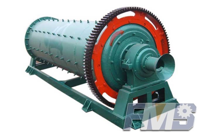
SAG Mill Efficiency
The energy efficiency of tumbling mills can be examined directly by looking at the motion of ore and grinding balls inside the mill. The makeup of the charge and the lifter bars attached to the inside of the mill shell can be designed particularly to maximize the mass of ore fractured per unit of energy spent. At the same time, the unnecessary collisions of steel balls against the mill shell can be reduced. Furthermore, the cascading charge flow can be altered in such a way as to maximize grinding efficiency. First, the shell lifters are designed in such a way that the motion is fully cascading and that part of cataracting motion is made to strike in the vicinity of the toe. In such a charge motion regime, both shearing action and impacts are fully utilized in grinding the ore.
The shell lifters are usually replaced once or twice a year. Pulp lifters survive for 2 or 3 years. The design of these two important mill components has been based largely on trial and error and hence varies considerably among manufacturers. However, over the years, important tools such as MillSoft and FlowMod have begun to help the designers analyze and understand the influence of the internal components of SAG mills—shell lifters, grates, and pulp lifters, respectively. The following sections discuss the basic principles and application of these two simulators.
MillSoft—Discrete Element Simulation of SAG Mills. The SAG mill is made up of a cylindrical shell with two conical shells attached on both ends. Lifter elements are attached in both the cylindrical and conical shell sections. As the SAG mill rotates, typically around 10 rpm, the internal flat walls of the lifter and shell impart momentum to the balls and rocks. The momentum is transferred primarily to particles in direct contact with the plate elements. These particles, in turn, impart their momentum to adjacent layers of particles. In this manner the motion of the entire charge evolves, resulting in what is commonly referred to as cascading and cataracting charge.
The discrete element method embedded in MillSoft replicates the evolution of charge motion as described above. In the simulation, the exact dimensions of lifters, plates, and balls are used. MillSoft can be used effectively to show the effects of different lifter configurations, mill loading, mill speed, and other operating conditions. Unlike single-particle trajectory programs that show only the outermost particle path, MillSoft takes into account the entire charge; one can effectively see the “kidney” shape of the charge, the dead zone, toe and shoulder of the charge, and areas of high impact on the mill lifters.
MillSoft also can be used to follow lifter wear, shell plate wear, and particle breakage. Most importantly, the location and the intensity of impacts on lifter bars can be recorded computationally, and a corresponding metal abrasion at that location can be worked out. In a like manner, the energy of impact can be used to fragment the rock particles in the simulation. However, the distribution and number of fragments produced overwhelm the computational task, and hence, this computational path is rarely followed.
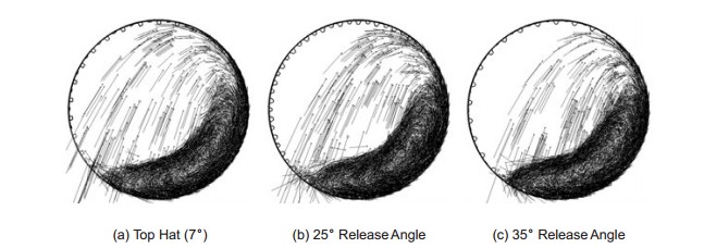
Shell Lifter Design and Charge Motion Analysis with MillSoft. A typical example of charge motion analysis with MillSoft is described in this section. The SAG mill under consideration is a 38u24-ft mill drilled for 60 rows of shell lifters. Therefore, the mill can be fitted with a set of 30 high and 30 low lifters or a total of 60 high lifters. The total charge is 27% with 15% balls. The mill is expected to draw 15–18 MW power. The mill speed is set at 76% critical speed.
Figure a shows the SAG mill fitted with traditional lifters. The high lifters are the top-hat type with a 7˚ release angle. The velocity vectors are superimposed on the balls and the rock particles. The central region reveals where grinding action is minimum. Due to the small release angle, a considerable amount of rock and ball particles are thrown against the mill shell. The ball-to-liner strike zone extends as high as the nine o’clock mark. The mill may not reach design capacity, especially with a hard ore type. Furthermore, considerable damage to liners is imminent within 4 months of operation. Next, we consider the same mill fitted with 30 high lifters and 30 low lifters of a 25˚ release angle. Figure 3b shows the snapshot of charge animation. Here, ball strikes on liners are seen nearly up to the eight o’clock position, a considerable improvement over that shown in Figure 3a. This lifter is suitable for maintaining a moderately aggressive charge motion at the expense of shorter lifter wear life.
Next, the release angle is increased to 35˚ with 30 high lifters, as shown in Figure 3c. The cataracting charge lands within the toe of the charge. This type of charge motion is ideal for SAG mills in order to preserve the life of shell lifters. The mill speed may be increased without fear of damaging liners. The Alumbrera mines exploited this concept to increase production. With such lifters, Alumbrera even used 150-mm top ball size.
Get Detail Information:
(If you do not want to contact to our online customer service, please fill out the following form, Our client manager will contact you later. We will strictly protect your privacy.)