Operation of SAG Mills
The processing capability of a SAG mill is greatly affected by ore geology and operating variables within the mill. The key issues broadly can be classified into two categories: field of breakage and charge motion, and flow through the grate and pulp lifters. The field of breakage and charge motion are affected primarily by the design of shell lifters and mill speed. Once the ore is ground to a size that can pass through the grate holes, the slurry flows into the pulp lifter chamber that transports it into the discharge trunnion. These components of the SAG mill are schematically shown in Figure blow.
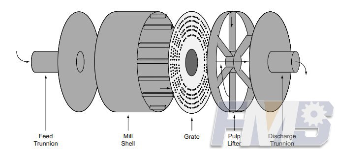
Schematic of a typical SAG mi
Once the slurry has made its way via the grinding media charge, its first stage of discharge is via the grate. Hence, in the absence of any subsequent restriction, the maximum flow capacity that can be obtained for a given mill is determined by the grate design. Here, the design variables are the open area and radial distribution of slots. The driving force for slurry transport from the mill shell through the grate holes is the difference in pressure head across the grate.
Field of Breakage. The motion of charge or rocks and balls in SAG mills can be viewed as a field of breakage generated as a result of the internal profile of the lifters and the rotational speed of the mill shell. The ore entering through the feed port is ground by this field and, after being sufficiently ground to the grate slot size, the slurry leaves through the slots in the grate. The field of breakage influences the rock mass in the SAG mill. Should the incoming ore be harder and the field of breakage insufficient to reduce the size, the ore stays in the mill longer because it is unable to pass through the grate. The net effect is an increase in rock mass, and the feed rate to the mill must be decreased appropriately to maintain rock-to-ball ratio. On the other hand, when the ore is soft, the field of breakage reduces the ore size rapidly, and hence the rock mass decreases. To sustain a set rock mass, the feed rate must be increased. The complicating factor is that the incoming ore feed itself determines the breakage field.
Flow through the Grate and Pulp Lifters. Discharge grates and pulp lifters play an important role in performance of the autogenous and semiautogenous mills. The performance of the pulp lifters in conjunction with grate design determines the flow capacity of these mills. The function of the pulp lifters is simply to transport the slurry passing through the discharge grate into the discharge trunnion. Its performance depends on the mill size and design, the grate design, and mill operating conditions, such as mill speed and charge level. The difficulties associated with slurry transportation from SAG mills have become more apparent in recent years with the increasing trend to build larger-diameter mills for grinding high tonnages. This is particularly noticeable when SAG mills are run in closed circuit with classifiers such as fine screens or hydrocyclones.
The performance analysis of conventional pulp-lifter designs shows that a large amount of slurry flows back from the pulp lifter into the mill . The backflow depends on the size and design of the pulp lifters. The back face of the pulp lifter is the grate itself, so that the slurry readily flows back into the mill. Subsequently, the field of breakage diminishes when excessive slurry builds in the mill.
Charge Motion. In a concentrator, all of the auxiliary equipment (i.e., pumps, conveyers, screens, and hydrocyclones) and two primary resources (i.e., steel and electricity) primarily serve to maintain grinding action in the belly of the SAG mill. It is this action that dictates capacity. Therefore, this grinding action should be observed continuously from the control room so that the necessary steps can be taken to keep the grinding field at its highest potential. Unfortunately, the grinding environment within the mill shell is very severe, and none of the online instrumentation developed so far is able to survive the continuous impact of large steel balls. Direct observation is impractical, therefore, the next available option is a simulation of the grinding field to gauge the intensity of grinding or the lack of intensity of grinding.
Mill Power Draft. The field of breakage and flow through the grate and pulp lifter influence each other, and the net effect is the buildup of a holdup level in the mill, which draws a certain power, and this power draft is clearly linked with mill throughput. If the interaction can be understood, then mill capacity can be determined much more clearly. Then the expectation of increasing capacity at the same level of power draft by one means or another can be safely evaluated.
The power draft of a SAG mill and its consequences are illustrated in Figure 2, wherein 5 days of operating data in a 32u14-ft SAG mill is plotted. The power draft of the mill is held between 6 and 7 MW, whereas tons per hour (tph) of ore feed to the mill shows wide variations between 1,000 and 1,600 tph. Figure 2 shows that the feed rate drops whenever the power draft shows an increasing trend, whereas intuitive reasoning would suggest that feed rate should be proportional to power draft.
The data show that the specific energy consumption (kWh/t) of ore is not steady, as one would expect for a typical ore body. Even within a 24-hour time frame, where the feed ore hardness may be assumed constant, the variation in feed rate is dramatic. The internal dynamics within the SAG mill, as exemplified by the three broad concepts, are causing wide fluctuations in grinding rate, which in turn is reflected as capacity.
Tagged: Operation of SAG MillsSemi Automatic Milling MachineSAG MillSAG Grinder
Get Detail Information:
(If you do not want to contact to our online customer service, please fill out the following form, Our client manager will contact you later. We will strictly protect your privacy.)


